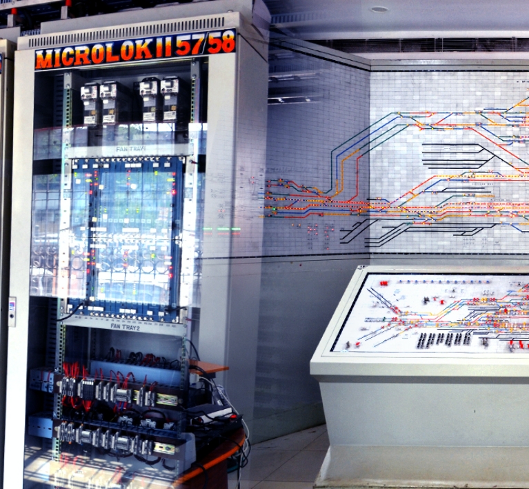
K5BMC is an Electronics Interlocking System which developed by Kyosan Electric Mfg. Co. Ltd. This is Japan based Interlocking System. It design based on the Solid State Interlocking Interlocking System. This System Supply Japan, China, Korea, India, USA, Singapore, Nepal & Bangladesh.
Table of Contents
Architecture of Kyosan EI system :
- K5BMC has 2 out of 2 architecture HW & SW
- It has redundant pair of CPUs; work on Checked-redundancy mode – safe
- Its logic unit & Peripherals are duplicated – high system availability
- Software tool (Logic Data Compiler-LDC) – easy to use, programmable as an image of Relay, easy alteration
- Cards are interchangeable between Installations
K5BMC :
K – Kyosan
5B – Model no
M – Multimode
C – CAN (Control Area Network, Communication Protocol)
Advantages of K5BMC :
One of advantages of KBMC is it’s having separate modules for-
- Logic functioning – Logic Sub rack Module (LK7-C)
- Vital I/O function (OC) – ET/EP5 – Sub rack
- Non-vital I/O function (MMIF) – EM6 Sub rack
- Journal Module – Data logger communication
K5BMC Hardwires :
- LK7-C Sub rack
- EP5 Sub rack (Vital OC)
- EM6 Sub rack (MMIF)
- PCINIO2
- SPHC – TT
- SPHC – PW
OTHER HARDWARES:
- TCF -142
- NIVOX – FRMC
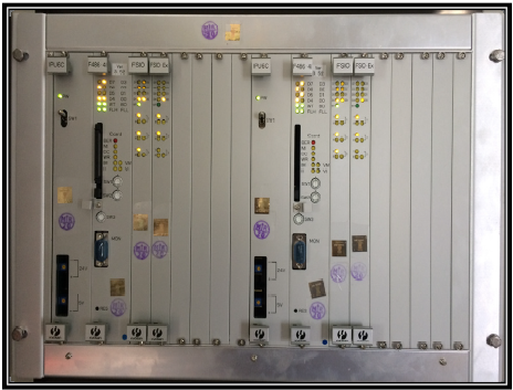
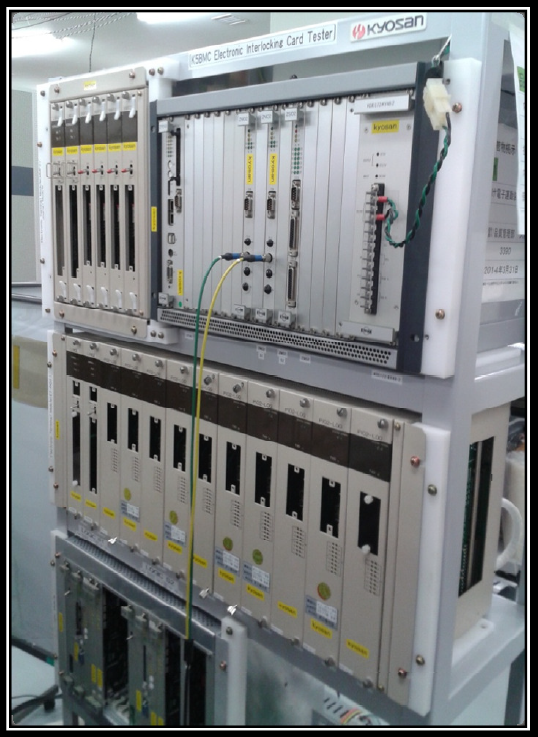
LK7-C SUB RACK – Logic sub rack:
- Mother Board.
- IPU-6C
- F486-4I
- IC-CARD
- FSIO
- FSIO-EX
- DID
- FIO7
- EX-FIO7

Mother Board :
- The Logic sub-rack is a enclosure arrangement which contains a mother board.
- The Motherboard is designed in such a way that both front and back side cards can be accommodated.
- The mother board used to accommodate various kinds of PCB and it’s allows communication with one another through VME (Versa Modular Euro) Bus.
- VME bus is a bus (Computer data path) system.
- VME bus is a hardware. No Software runs on it.
- VME bus system withstand shock, vibration, and extended temperatures better than the buses used in computers.
- It Consists of 20 slots. First 1-10 Slots were assigned for System1 & 11-20 Slots used for System2.
- System 1 & System2 are two identical units.
VME BUS :

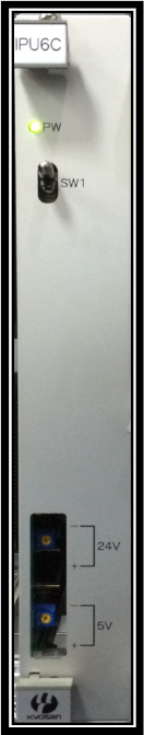
IPU6C :
- IPU6C is a Power Supply card for each card in the Logic Module.
- The first two Slots of Logic Sub rack is used to accommodate IPU6C.
- The Input Voltage is DC 24V + 10%
- The Output Voltages are DC 24V + 10% and DC 5V +5%, -0%
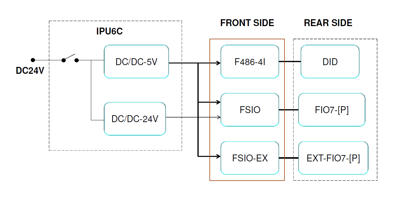
- It provides the isolated power supply to the each card of the Logic Module through built in DC-DC converter.
IPU6C – Power Distribution Diagram :
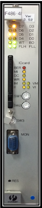
F486-4I (K5BMC CPU Card):
F486-4I is basically an microprocessor based CPU card.
- The Main task of F486-4I is processing the interlocking circuit by reading station based data from IC card and driver data for inputs and outputs of each I/O card.
- F486-4I is a Fail safe 32 bit Intel processor CPU PCB.
- It’s Operating Frequency is 40MHz.
- 2 out of 2 Architecture.