Hitachi EI is also Known as Ansaldo EI. The product name of this System is Microlok-II. This System is very much user-friendly for Indian Railways. Microlok II is a microprocessor based electronics interlocking System. It is a Single Processor system with diverse (dual) Software with extensive safe checks.
Table of Contents
Hardware :
MLK II hardware consists pf the following components:
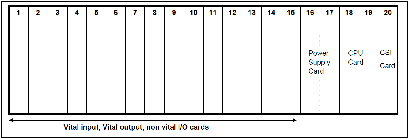
Card File:
- Slot No. 1 to 15 & 20 accommodate Non-Vital Input/Output or Vital Input or Vital Output boards. (Slot No. 20 is used to accommodate Coded System Interface Card or CSI Card for CTC.
- Slot No. 16 & 17 accommodate Power Supply Board.
- Slot 18 & 19 accommodate CPU board.
CPU Board:
The CPU board is controlled by Motorola 68332 microprocessor and stores the
Executive and Application software. It contains the central controlling logic and
diagnostic monitoring for the Microlok II system, and provides five serial data ports to
communicate with peripheral devices.
- Ports 1 and 2 (RS-485 type) – for communication with other MLK systems.
- Port 3 (RS-423/232 types) – for communication with non-vital control system such as operator’s PC/VDU Panel/CTC/Genesys.
- Port 4 (RS-232 type) – for communication with non-vital control system such as VDU panel/CTC/Genesys/Indication Panel.
- Port 5 (Debug port) (RS-232 type) – for communication with Maintenance PC for debugging.
Indications and buttons are avilable on front side of the CPU card as shown in below figure:
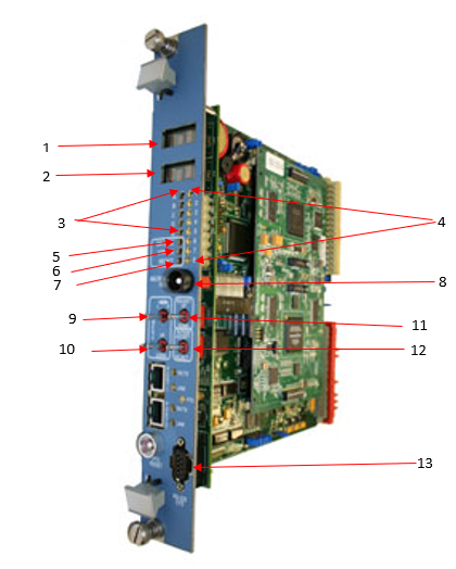
| Fig. Ref | Label | Device | Purpose |
| 1,2 | (None) | 4-character alphanumeric displays | On-site configuration programming menus and options. |
| 3 | A,B,C,D,E | Yellow LEDs | Reserved for serial link status. |
| 4 | 1,2,3,4,5,6,7,8 | Red LEDs | User-defined in application software |
| 5 | ON LINE | Green LED | When lit, indicates normal system operation (successful diagnostics). |
| 6 | VPP ON | Yellow LED | When lit, indicates FLASH +5V or +12V programming voltage enabled (via board jumper). |
| 7 | RESET | Green LED | When lit, indicates that the system is in reset mode. |
| 8 | RESET | Momentary pushbutton | When pressed, resets the CPU. Also used to place the CPU in the reset mode. |
| 9 | MENU L-R | 3-position (return-tocenter) toggle switch | Used to search main program menu items shown on displays. |
| 10 | MENU UPDOWN | 3-position (return-tocenter) toggle switch | Used to select main program menu items shown on displays. |
| 11 | ADJUST UPDOWN | 3-position (return-to center) toggle switch | Used to cycle through configuration values to be selected with “ACTION” switch. |
| 12 | ACTION ACCEPTREJECT | 3-position (returntocenter) toggle switch | Executes or cancels configuration value selected with “ADJUST” switch. |
| 13 | RS-232 DTE Diagnostic Link Connector | DB9, RS-232 Connector (DTE) | Used for connection to Maintenance PC for System monitoring diagnosis. |
Power Supply Board
The power supply board performs the following functions:
- Converts the external supply voltage (9.8V to 16.2V DC) to regulated +12V and +5 needed for the operation of the cardfile circuitry.
- Provides an isolated source voltage for external contact sensing.
- Supplies energisation voltage to the VCOR relay coil under the control of the CPU board.
- As long as CPU detect no internal/external system faults, it sends a 250 Hz check signal to PS PCB which in turn holds the VCOR relay in pick up condition.
- Failure of a diagnostic check results in removal of check signal thereby deenergisation of VCOR. This results in removal of power to all vital system output.
Power input to the system
- Voltage range: 9.5 to 16.5 V DC
- Min. Voltage: 12 V DC
- Min. System Start-Up Voltage:11.5 V DC
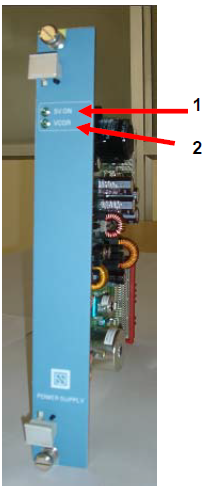
| Fig. Ref | Label | Device | Purpose |
| 1 | 5V ON | LED (green) | When lit, indicates 5Voperating power on to other cardfile PCBs (If not lit refer to Figure- |
| 2 | VCOR | LED (green) | When lit, indicates conditional power on to VCOR relay (CPU diagnostics normal). (If not lit refer “CPS CLEAR FUNCTION” details in Figure |
Non-Vital I /O Board
- The Non-Vital I/O board is designed to receive non-vital inputs (controls) and generate non-vital outputs (indications).
- Each PCB provides 32 inputs and 32 outputs through its rear 96 pin connector.
- Available in 12 V and 24 V DC applications.
- Non-vital inputs – Panel push buttons and keys.
- Non-vital outputs – Panel indication LEDs, counters and buzzers.
- LEDs are available on the front panel to show the status of non-vital input/output.
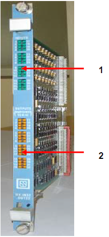
| Fig. Ref | Label | Device | Purpose |
| 1 | INPUTS 1-32 | Green LEDs | Monitors states of non-vital inputs 1- 32. When LED is lit, respective input is on. |
| 3 | OUTPUTS (SWITCHED TO N12) 1-32 | Yellow LEDs | Monitors states of non-vital outputs 1- 32. When LED is lit, respective output is on. |
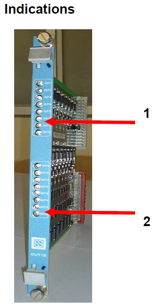
Vital Output Board:
- Each Vital Output PCB is having 16 independent 24 V outputs.
- Each output is assigned to the final relay which is driving the outdoor signalling gears such as HR, DR in case of signal & WNR, WRR in case of points.
- Since the output boards are driving outdoor gears, they are continuously monitored by the CPU and any abnormal voltage present in the output will lead to system reset / shutdown to ensure safety.
| Fig. Ref. | Label | Device | Purpose |
| 1 | OUT1-OUT8 | Yellow LEDs | Monitor state of vital outputs 1 through 8. When lit, indicates respective output is turned on. |
| 2 | OUT9-OUT16 | Yellow LEDs | Monitor state of vital outputs 9 through 16. When lit, indicates respective output is turned on. |